Upgrading the Carrera McLaren M20
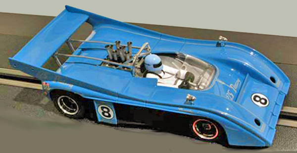
We really like the Carrera 1/32 scale CanAm cars, especially the McLaren M20 There is something about the M20 that seems to make it the very picture of what a CanAm car should be. Carrera’s M20 model, along with other recent Carrera cars, incorporates features that make it a big improvement over the company’s previous products. It looks good and drives well out of the box, which has only fairly recently become the case with Carrera cars. But the Carrera M20 still leaves room for improvement.

For one thing, we have never understood why the Carrera designers think they have to put so much more stuff inside their cars than other manufacturers do. All that wiring, the circuit board, the reversing switch, the needlessly complicated design of the guide, and all the bumf needed for digital conversion — they all add weight and complexity, but for most users they are essentially useless. In addition, we have never thought the FF motor, as good as it is for some applications, is a proper motor for a Can Am car. So, when a semi-junk M20 wandered into our workshop we just couldn’t resist stripping all of it out and starting over.

We have to give the Carrera designers full marks for one thing — the whole lashup comes out of the car as a unit just by removing three screws.

Our motor for this project is a Slot It Flat 6. The Flat 6 configuration is made to order for CanAm cars and other cars with low, aerodynamic bodywork. The Flat 6 easily clears the underside of the body. One thing that makes it a lot easier is that Carrera didn’t try to put a full-depth interior in the car. This particular Flat 6 variant has performance characteristics that make if suitable for use with standard race set power supplies.

The first step in modifying the chassis is to cut the front motor mount out as shown above.

We are going to turn the front mount 180 degrees in the chassis, making what was the front face of the mount now the rear face (toward the motor). The hole in the mount for the shaft bushing has to be enlarged slightly to fit the Flat 6’s larger bushing. This also needs to be done to the rear mount.

The next step is to cut out the entire part of the chassis under the motor. The height of the Flat 6 is just enough greater than that of the FF that it will sit in the car with it’s bottom face flush with the bottom of the chassis. The next step is to cut out a rectangular area forward of where the motor will sit into which the front mount will be glued.

This photo shows how the front mount fits back into the modified chassis. We glued it into place with medium CA glue.

To replace the original Carrera guide we needed to have a whole new guide mount. Instead of fabricating one we just rummaged through our box of discarded chassis to find a donor for this vital component. We found a Monogram Greenwood Corvette chassis and cut out the guide socket and the area of the chassis back to the front of the motor mount as shown here. This shows you why you should never throw away broken, worn-out or obsolete chassis.

Here’s the M20 chassis with modifications completed. They include:
1. A strip of thin styrene glued to the bottom of the chassis under the rear mount to keep the motor from rotating in the chassis.
2. Small pieces of sheet styrene CA glued into the chassis to strengthen the chassis by filling in the spaces left by the cutting we did earlier.
3. A length of styrene strip glued to the top surface of the chassis to reinforce the area where the front motor mount was glued in.
4. The Greenwood Corvette guide mount CA glued into place.
5. The opening for the guide extended forward to the curved rib (6) that reinforces the front of the chassis. This allows the guide to be mounted a little farther forward than before, increasing the guide lead for improved handling. The guide could actually be moved farther forward than this if you want to, but we preferred to retain the curved rib for the strength it provides.

All that remained to do to complete the modifications was to give the chassis a coat of black paint for appearance and snap all the components in. The guide is a stock snap-in part from a Slot It Porsche 962. We had to take a little material off the top of the guide socket to enable the guide to turn freely. We cut the lead wires to a little more than half their original length. The pinion gear is a stock Scalextric part. We had to cut about 1/16″ off the end of the 2mm motor shaft to keep it from binding on the Carrera gear’s alignment ring, which was positioned for a 1.5mm shaft. Gear mesh is now adjusted with a thin spacer between the left rear wheel and the axle bushing. You could, of course, replace the gears or the entire rear axle assembly with aftermarket parts. The retainer that snaps in above the traction magnet to hold it in place is visible just below the pinion gear.

As you can see in this photo of the car with the body sides removed, the Flat 6 fits under the McLaren body with clearance to spare. You probably could get an FK180 in there but to keep the mount modifications simple and avoid having either the motor shaft center above the axle center or the bottom of the motor below the bottom of the chassis the Flat 6 is the way to go. And, of course, there are other cars you might want to try this with in which the underbody space isn’t so generous.
With the chassis work completed it’s no great trick to correct the body’s excessive height above the chassis and tires. This is a faux pas common to no small number of slot cars, and just about every manufacturer has committed it on occasion. For examples, see our on-line articles on the Monogram Lola T70 and McLaren M6, as well as the Scalextric Mustang FR500S.
In the photo above you can see a rather unseemly gap between the fenders and the tires as well as a good deal of clearance between the top of the motor and the bottom of the interior tray.

To remedy this lapse on the part of the Carrera designers, first remove 1/16″ of material from each of the areas highlighted in red above.

Next, cut off the socket that extends downward from the bottom of the interior as shown in red, and remove 1/16″ from the length of each of the four body posts. You should also remove or grind some material off the bottom of the little buckets behind the brake cooling holes in the front fenders. We just pulled them off. You will also need to grind a little off the very bottom of the two silver-colored struts under the wing to get them to fit properly.
Then just remount the body on the chassis and you get this:

Much better, isn’t it? We will also have to cut 1/16″ of the body sides before we reattach them (and it will be to the body, not the chassis). We’ll show you that in an upcoming issue.
If you have comments or questions about this article please do not use the comment function in the blog. Rather, send them to support@electricdreams.com. Your messages will be read and responded to.
There is more to come! We will add new sections to this article as we publish them in our e-newsletter. You can subscribe to it free of charge on our home page.


Can you build a car for me ?